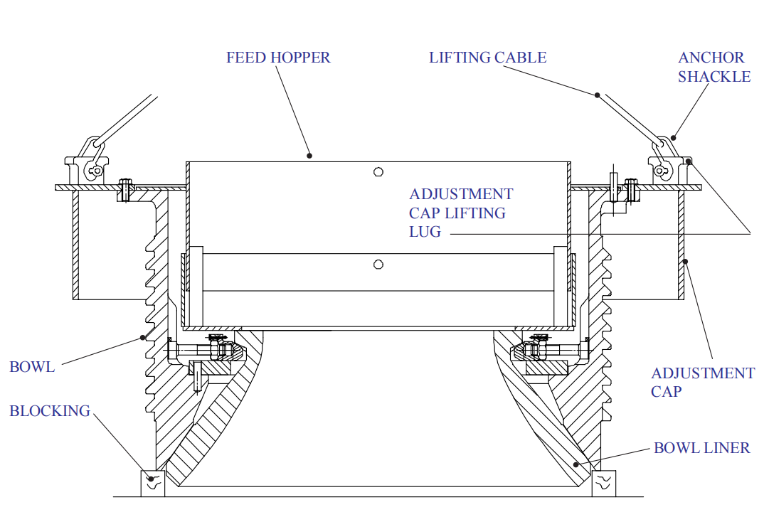
Cone Crusher Bowl Assembly
What is cone crusher bowl assembly?
The cone crusher bowl assembly covers the bowl, bowl liner, and hopper assemblies. The bowl which is threaded on its outside diameter is suspended on heavy-duty threads inside the adjustment ring. The bowl is adjustable, up or down, by turning the bowl counterclockwise or clockwise within the adjustment ring. Adjusting the bowl controls the size of the feed opening and discharge setting.
The adjustment cap which rests on top of the bowl and contacts a lip seal on top of the dust shell bolted to the adjustment ring provides only a protective cover for the bowl and clamping ring. A series of spring-loaded clamping cylinders located around the top of the adjustment ring pushes upward against the clamping ring and raises the bowl into the crushing position. The bowl turns with the adjustment cap when the cap is rotated by a heavy-duty hydraulíc motor adjustment mechanism mounted on the adjustment ring.
The feed hopper which is set over dowels in the flange at the top of the bowl directs the incoming feed into the crushing chamber. Fiberglass insulation packed around the top of the bowl liner seals out the crushing dust at the bottom of the hopper. The bottom of the hopper and the hopper shell form a ledge where the feed will accumulate providing a dead bed that protects the hopper surface from the constant flow of incoming feed.
Directly beneath the feed hopper and recessed in the bowl are a series of wedges or bolts which hold the replaceable bowl liner rigidly to the bowl. The liner, while it is adjustable, is the stationary crushing member.
Bowl assembly instructions
If the bowl, bowl liner, and hopper assemblies have been shipped separately due to weight or shipping restrictions, the various assemblies must be dismantled, cleaned, and reassembled prior to installation as follows:
- In order to expose the full length of threads on the bowl, it will be necessary to first remove the adjustment cap. Remove the capscrews and lock washers holding the adjustment cap to the top of the bowl. Lift the adjustment cap off the bowl by rigging cables and anchor shackles to the lifting lugs on the adjustment cap.
- Thoroughly clean the threads on the bowl, adjustment ring, and clamping ring, removing all dirt and rust preventive.
- Rub down all thread surfaces on the bowl, adjustment ring, and clamping ring using a cloth soaked with molybdenum disulfide powder.
- Liberally coat the threads with a mixture of grease and 5-10% disulfide powder.
WHEN CRUSHING HOT MATERIAL SUCH AS CLINKERS OR SLAG, A HIGH-TEMPERATURE GREASE MIXED WITH 5-10% (BY VOLUME) OF MOLYBDENUM DISULFIDE POWDER SHOULD BE USED. THIS SAME POWDER MIXED WITH LUBRICATING OIL HAS ALSO BEEN FOUND SATISFACTORY FOR SUCH APPLICATIONS.
- Reassemble the adjustment cap and other components to the bowl.
- Lift the entire assembly onto the clamping ring by using the same lifting procedure. The clamping cylinders must be DEPRESSURIZED before the bowl assembly can be turned into the clamping ring and adjustment ring.
- Turn the bowl into the clamping ring and adjustment ring.
Bowl assembly removal
To remove the bowl assembly for the inspection and replacement of parts, proceed as follows:
- The clamping cylinders must be DEPRESSURIZED before the bowl assembly can be turned out of the Crusher.
- Turn the bowl counterclockwise out of the adjustment ring using the hydraulic motor adjustment mechanism.
- By rigging cables and anchor shackles to the lifting lugs on the adjustment cap, lift the bowl over the feed plate assembly, then lower it onto wooden blocking.
If you have any questions or inquiries about cone crusher parts, please contact us freely!

 Download Brochure
 Product List


